Archetype12 design notes — a test board for choosing the next sensor by measurement
Why a second test board
The first thing to settle for the next ReLow60 models (US / Split / JP, and ReOrtho60) was the sensor. The MT9102ET used in the Limited Alpha measures fine on both self-heating and temperature drift. I went looking again anyway, because I wanted to know whether there was another step of resolution to be had.
Sensors cannot be compared from datasheets. Sensitivity and linear range depend on the distance to the magnet, and that distance is set by board thickness, plate and switch. The only fair comparison is to put the candidates on the same board, under the same switches, in the same conditions as the product. That board is Archetype12.
Its predecessor, Archetype09, asked whether a low-profile magnetic keyboard could be built at all. This one asks what to build it with.
How the shortlist formed
The starting point was a judgement: bipolar Hall sensors are already close to their physical ceiling with the MT9102ET. Swapping part numbers within the same principle buys little. So the candidates came from different principles.
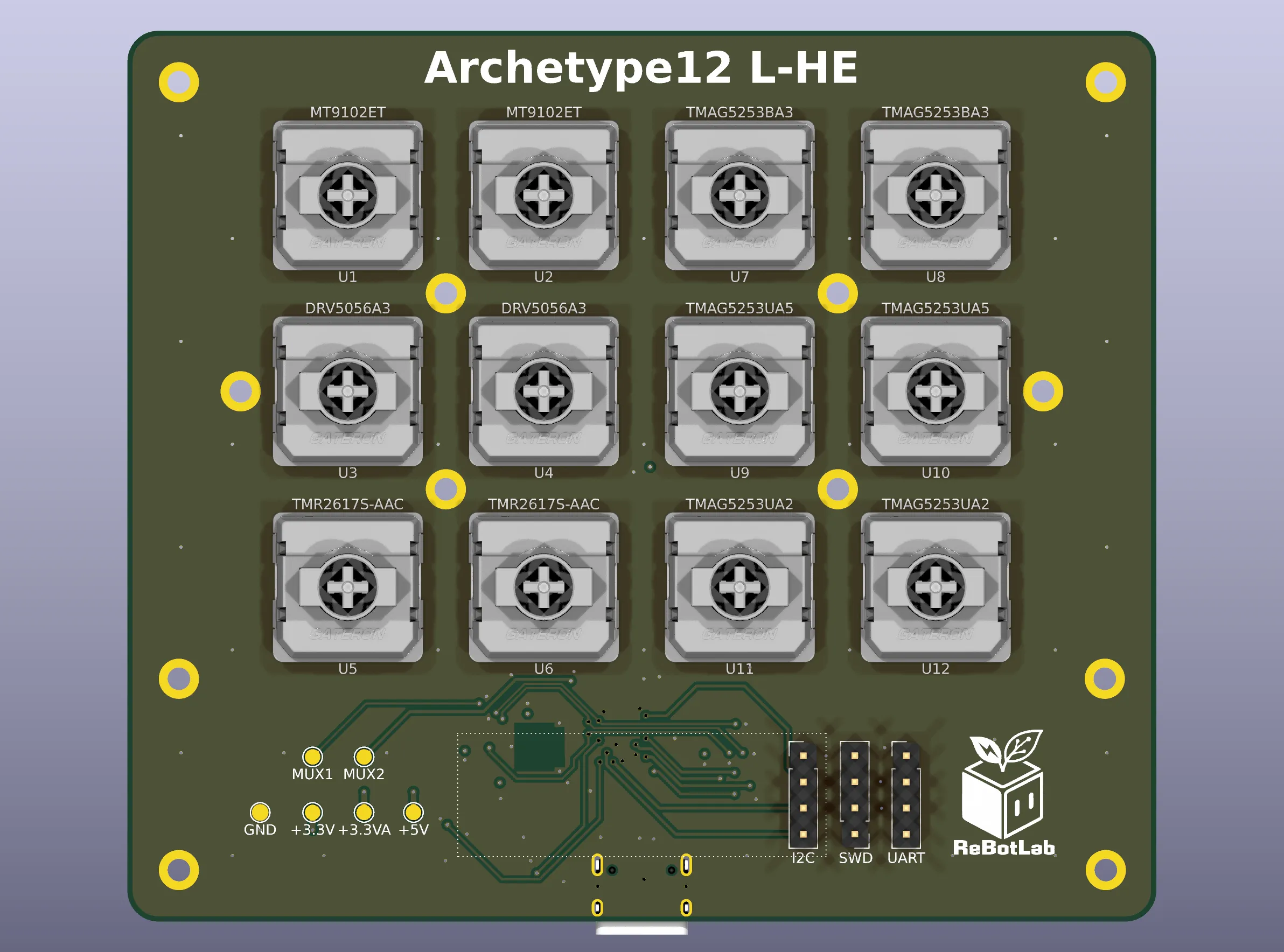
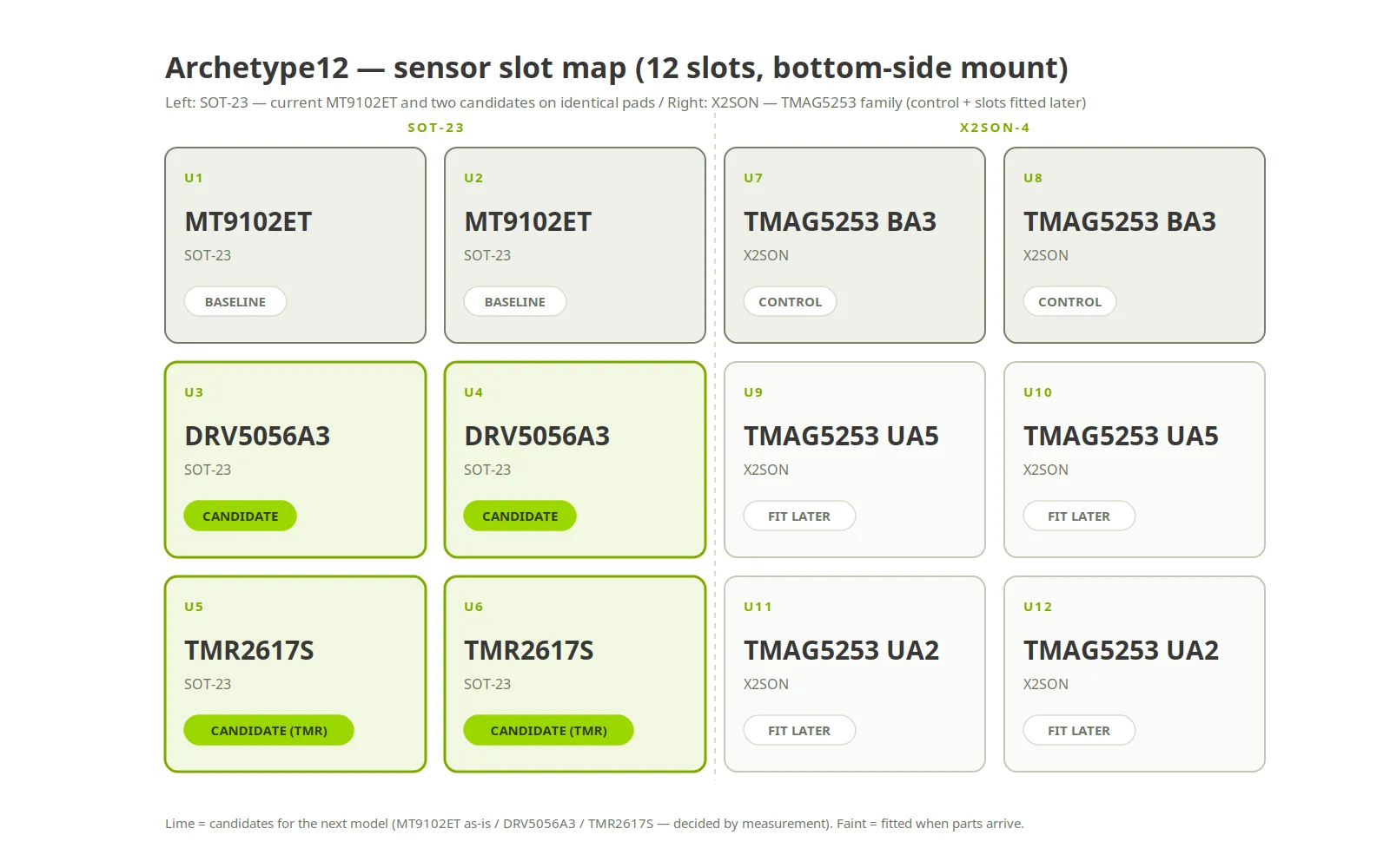
- DRV5056A3 (TI) — a unipolar Hall sensor. Roughly 1.9× the sensitivity, with compensation for the magnet’s temperature coefficient built in
- TMR2617S-AAC (MDT) — a tunnel-magnetoresistance sensor, 2–2.8× the sensitivity. But TMR has hysteresis, so the reading may differ between press and release. That is the thing the measurement has to settle
- TMAG5253 family (TI) — X2SON package. BA3 as a control; UA5 / UA2 are high-gain but hard to source, so they go into spare slots later
The candidate that got dropped
The DRV5056 A8 grade was in the plan at first, on the strength of a “zero-point temperature drift of 0” in the datasheet. Reading it again turned up two mistakes.
- Its linear range is only 64 mT. The measured flux at bottom-out on a 1.5 mm switch is 66.4 mT, so the deepest part of the stroke would clip
- Magnet temperature compensation is not what sets the A8 apart. Every A grade from A1 to A8 has the same +0.12 %/°C compensation; only the Z grades lack it
So the A8 had nothing over the A3 and one thing against it. Its slot went to the TMR2617S instead.
Three candidates on one pad
While making that swap I checked the TMR2617S datasheet and found its SOT-23 pinout is 1 = VCC / 2 = VOUT / 3 = GND — identical to the MT9102ET and the DRV5056. The original plan had solder jumpers to rearrange pins. They turned out to be unnecessary: all three candidates drop onto the same pads, and by the same token any of them fits the current production footprint unchanged.
Designing one board that compares six parts fairly
Why four layers
Archetype12 is a four-layer board. Two would look sufficient for a test board, and the reason it is not goes to the heart of what this board is for.
The flux a sensor reads passes through the inner copper on the way in. A different layer structure means the numbers measured here no longer correspond to the production board. Measuring the actual ReLow60 production PCB gave F.Cu and In1 as GND, In2 as +3.3VA and B.Cu as GND, so Archetype12 uses the same four layers with the same assignment. There is a general argument that In2 should be GND as the reference plane for B.Cu signals. This board deliberately does not follow it: the moment the copper distribution differs from production, the measurement stops meaning anything.
Everything on the back
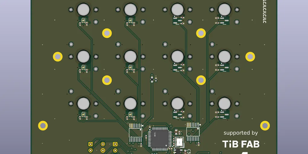
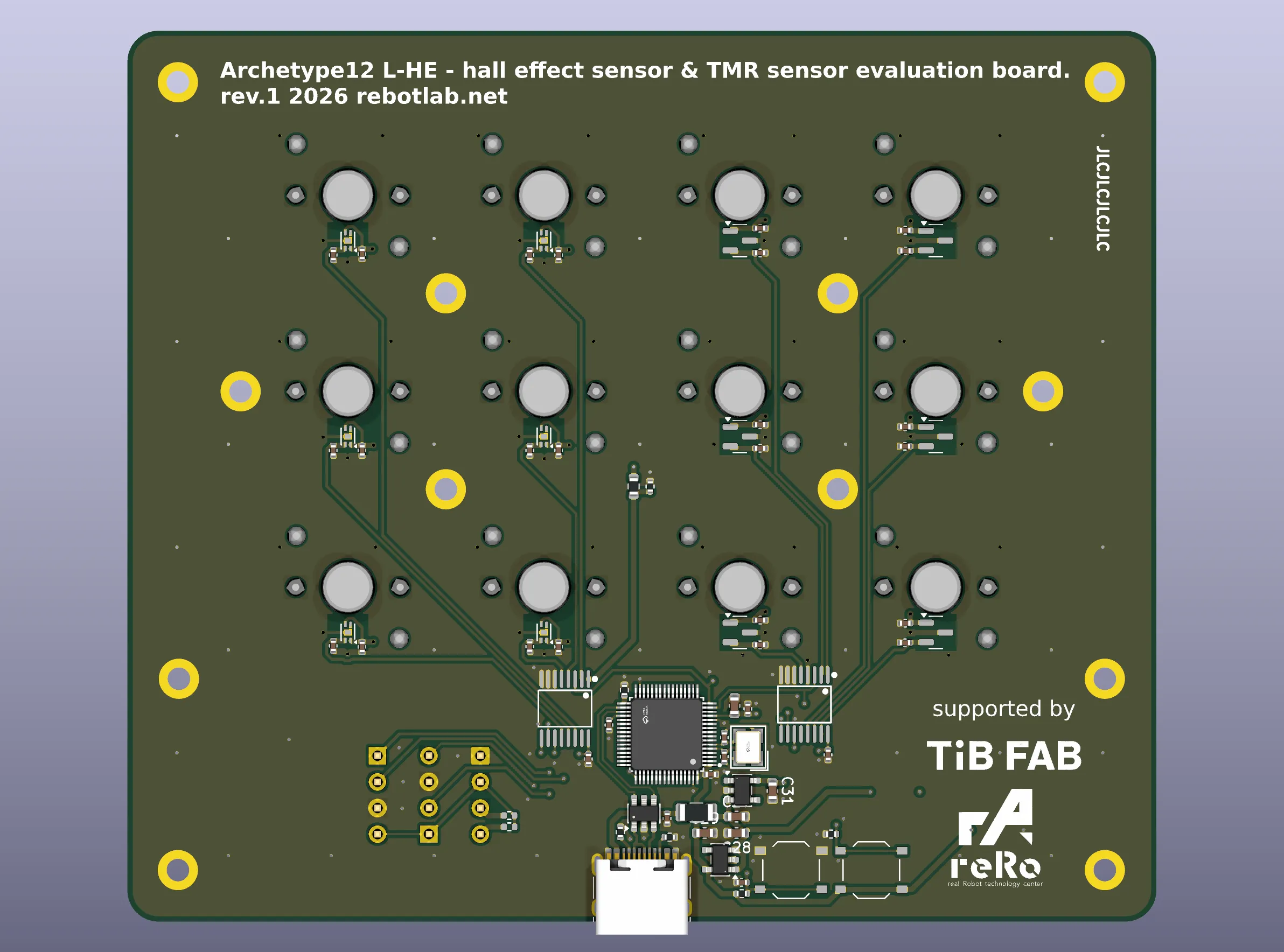
The front carries only switches and mounting holes. Sensors, multiplexers, MCU and power all live on the back. Back-side sensors mirror ReLow60, where the magnet-to-sensor distance is set by the 1.2 mm board thickness. Each multiplexer sits directly under the columns it serves, so the twelve analog traces stay short.
Mounting holes were also placed where four keys meet. The board can then be clamped right next to the keys whose plate-to-PCB gap is being measured, which matters for the gap experiment.
The measurement plan — two groups, to keep confounders out
Putting six parts on one board raises two worries: that neighbouring sensors heat each other, and that the board heats unevenly. Splitting the measurement into two groups avoids both.
Group 1, electrical (polarity, sensitivity, linearity, noise, coverage, effective resolution) is measured at room temperature. Neither neighbour heating nor oven uniformity is involved, so one mixed board measures as-is.
Self-heating is not measured per part. The current MT9102ET (6 mA) was soaked for five hours and drifted at most 4 LSB, which is small enough to call a non-issue. The DRV5056 draws the same 6 mA and will behave the same; the TMAG5253 (2.6 mA) and TMR2617S (0.3 mA) draw less and can only be better. That follows by deduction.
Group 2, ambient temperature (LSB/°C per part, zero drift, the effect of magnet compensation) is the one thing that is genuinely part-specific and has to be measured. Here the whole board is heated uniformly. A heat gun or a local thermocouple heats unevenly and ruins the comparison, so the first pass is on a hot plate and the real run is in an environmental test chamber, with a single thermocouple attached as a monitor rather than a heater. Heating the mixed board as one unit sends every part through the same temperature history, which is what makes the comparison fair.
And every key is measured pressed to bottom-out. Archetype09 was measured on partial travel with a height gauge and the saturation went unnoticed. Not again.
A mistake caught during design — the crystal frequency
When generating the schematic I had written the crystal Y1 as 8 MHz. It is 12 MHz. The source of the error was a parts table in a shared library’s README. Ordered as written, the board would have carried a crystal of the wrong frequency and USB would never have enumerated. It was pinned down by cross-checking three sources: the part number, the datasheet, and the ReLow60 shipping BOM. The lesson: a number in a description is not a primary source.
A prototype of the FSU
Archetype12’s plate and spacers are FR4 boards, 100 × 66 mm. Bolting plate, spacer and PCB together with M2 screws fixes the plate-to-PCB gap to the spacer’s thickness.
FR4 is stiff in compression, so the gap does not depend on how hard the screws are tightened. Spacers are made in 0.8 / 1.0 / 1.2 mm, and the gap is swept against flux and switch retention to find the best value. This structure — plate + spacer + PCB fixing the sensor distance — becomes the FSU (Fixed Sensing Unit) in the next models. Archetype12 is the board that chooses the sensor, and also the first physical FSU.
3D-printed spacers are for exploration only. FDM parts creep under compression and warp, so a thickness found with FDM does not carry over to FR4.
What comes next
Board, plate and spacers were ordered in early September 2026. Assembly is on my own hot plate (no parts on the front, so a single bottom stencil). TMR2617S samples are on order; the TMAG5253 UA parts go into the spare slots when they can be sourced.
Results will be written up once group 1 is in. Four things get decided in the end:
- Whether the DRV5056A3’s higher cost (1.9× sensitivity plus temperature compensation) is worth it over keeping the MT9102ET
- How much TMR2617S hysteresis is acceptable in practice
- The optimal plate-to-PCB gap, i.e. the spacer thickness
- Whether the next models’ main board should carry a temperature sensor IC