Archetype09
A test board for low-profile magnetic switches. Not for sale.
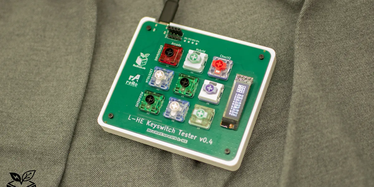
Overview
Archetype09 is a keyboard PCB featuring low-profile Hall effect sensors (magnetic switches). While keyboards using magnetic switches are gradually increasing in the custom keyboard space, very few use low-profile magnetic switches as their primary switch.
This board was designed as a test platform for the upcoming ReLow60 project. Its purposes include sensor selection, bypass capacitor selection, hybrid footprint testing, and firmware tuning. This project is developed based on peppapighs’ HE60.
60% Hall-effect keyboard. Contribute to peppapighs/HE60 development by creating an account on GitHub.
As this is a test board, there are no plans for sale, but it is published as a technical record of the design, manufacturing, and measurement process.
Key Specifications
| Item | Details |
|---|---|
| MCU | AT32F405RCT7 (ARM Cortex-M4, 216 MHz, USB High Speed) |
| Switches | Low-profile magnetic switches / Low-profile arcade magnetic switches / Hybrid footprint supporting both |
| Sensors | DRV5055A3 / MT9102ET / GH39FKSW |
| Key count | 9 keys (3 switch footprint types × 3 sensor types = 9) |
| MUX | SN74LV4051A-Q1 × 2 (8ch × 2 = 16ch) |
| ADC | AT32F405 onboard ADC (12-bit) |
| PCB | 4-layer board (JLCPCB) |
Component Selection
The general component selection follows the reference HE60. Each component is discussed in detail below, though all remarks reflect my personal assessment. For details and caveats on component selection, please refer to the HE60 documentation.
MCU - AT32F405RCT7
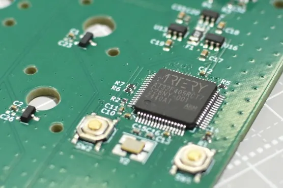
This MCU is low-cost and sufficiently capable. It is the same MCU used in the HE60. It is pin-compatible with the STM32F405 — essentially a clone of it. Despite being called a clone, it actually has a faster clock (STM: 168 MHz, AT: 216 MHz), providing more headroom than ST’s MCU for processing tasks such as the sensor scan rate ceiling.
Support for USB HS (High Speed) is also important. An MCU with USB HS support is required to achieve polling rates of 8000 Hz or higher. Without USB HS, the device falls back to USB FS (Full Speed), which limits communication to a maximum of 12 Mbps — insufficient for polling rates above 8000 Hz.
Switches - 6 Types
This board uses low-profile magnetic switches. This is my original contribution, not found in the reference HE60. Why low-profile? The answer lies in the switch stroke length.
For keyboards used in gaming, I believe shorter stroke length is better. This is not about response speed, however. In the era when mechanical switches were dominant, claims were made such as “low-profile switches have a shorter actuation point and are therefore faster” or “shorter stroke improves finger movement efficiency in gaming.” Now that magnetic switches are widespread, the actuation point can be set arbitrarily short, so the response speed issue is largely solved. However, stroke length is not a problem that magnetic switches have solved. In fact, with the proliferation of normal-profile magnetic keyboards, one could argue the situation has worsened. A longer stroke slows finger movement from bottoming out to pressing the next key. Conversely, a shorter stroke allows faster transition from bottom-out to the next key. In gaming, the time from bottoming out to the next keypress can affect operational efficiency and match outcomes.
That said, shorter is not unconditionally better. If too short, the risk of accidental actuation increases. A very short stroke reduces tactile feedback when pressing a key, making it harder to judge by feel whether the key has registered. Selecting an appropriate stroke length is therefore important. I consider 1 mm to be the practical minimum. There was a period when modding normal-profile switches with spacers to shorten travel was popular, but strokes below 1 mm tend to cause too many miskeys to be practical.
Touchscreen keyboards on tablets are a good example. The layout is standard QWERTY, yet most people find them harder to type on. I believe this is because the stroke length is zero — each key has no tactile feel, so there is no input feedback. The vibration feature during text input attempts to replicate a tactile sensation, providing virtual input feedback.
A shorter stroke also benefits actuation point precision in magnetic switches. Magnetic switches detect key travel as a change in magnetic flux density via a Hall effect sensor. Because magnetic force increases sharply as distance decreases, the closer the magnet operates to the sensor, the larger the flux density change for a given travel distance. Low-profile switches with shorter strokes are structurally well-suited to exploit this steep flux-change region. In a steep gradient, circuit noise is less likely to translate into positional error, allowing the Rapid Trigger actuation point to be set more finely and stably.
As mentioned earlier, normal-profile magnetic keyboards have become widely available. However, keyboards with low-profile magnetic switches remain rare — and in the custom keyboard world, there may not yet be a single one in existence.
tmyk is also building a low-profile keyboard. Thank you to the person who shared this information!
Here is a summary of currently available products using low-profile magnetic switches:
- Nuphy Air60 / Air75 HE (Low-Profile Magnetic Gateron Jade / Jade Pro)
- Melgeek Made68 Air (TTC KOM MINI)
- ZENAIM Keyboard (ZENAIM Keyswitch)
- Elecom VK720AL (RAESHA Low Profile)
- Logicool G515 RAPID TKL (unknown switch)
All of these keyboards are excellent, but they offer limited compatible switch options making switch swaps difficult, lack keycap compatibility, or have surprisingly long strokes. Aside from ZENAIM, none have received successors, suggesting they may all have been experimental products.
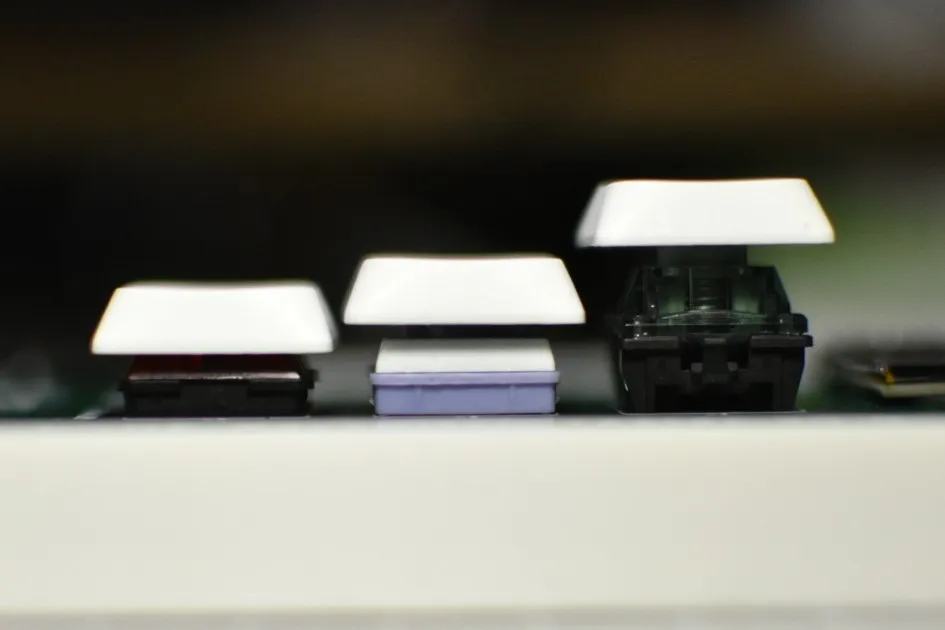
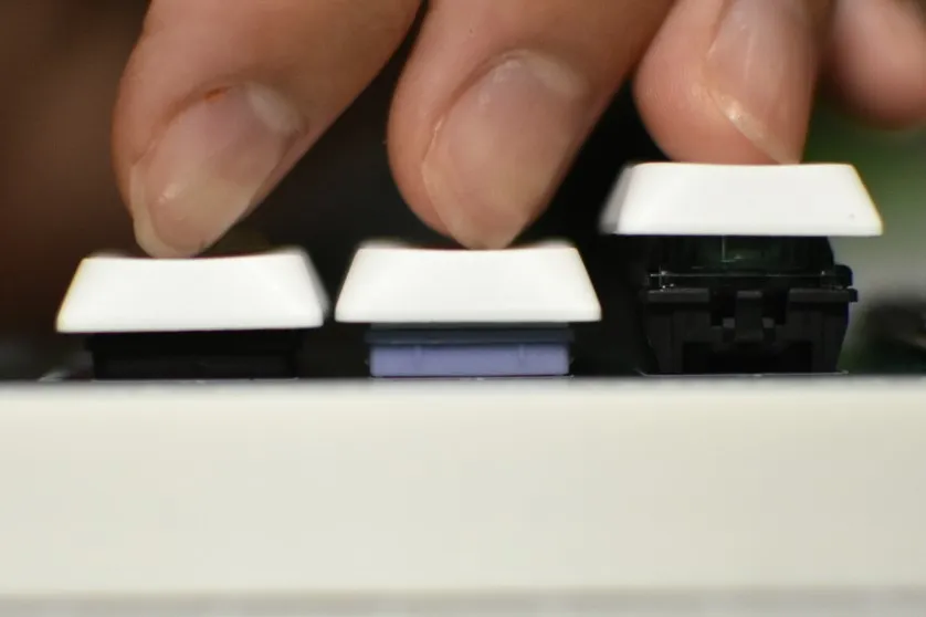
This project aims to support 6 switch types, all of which accept standard keycaps. They fall into two broad categories:
- ChocV2 — footprint similar to a ChocV2 mechanical switch. Presumed to share the same structure as ChocV2 except for the metal pins.
- Arcade — footprint similar to a low-profile arcade switch. Presumed to share the same structure as arcade switches except for the metal pins.
These two categories have different footprints.
This is my speculation, but just as today’s low-profile mechanical switches span various footprints (ChocV1, ChocV2, Arcade, Gateron Low Profile, etc.), I believe the same diversity has carried over into magnetic switches. As noted above, all switches adopted in this project are compatible with standard Cherry-compatible keycaps. Some profiles may not fit, but anything at or below Cherry profile height should clear without interference. Personally, I recommend low-profile keycap sets compatible with ChocV2, such as XVX Lowprofile, Nuphy nSA, or Nuphy Berry. Beyond set keycaps, ChocV2 is becoming mainstream in the custom keyboard world, making individual key retail and specialty keys relatively accessible.
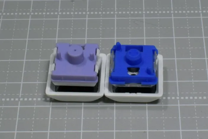
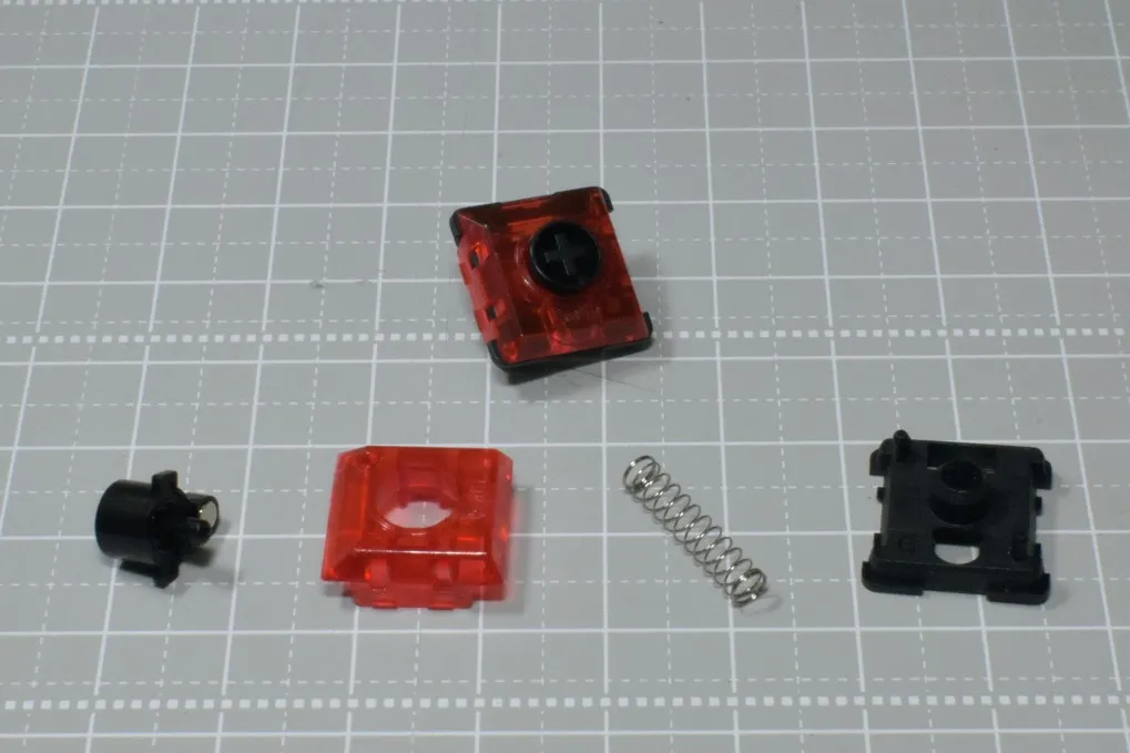
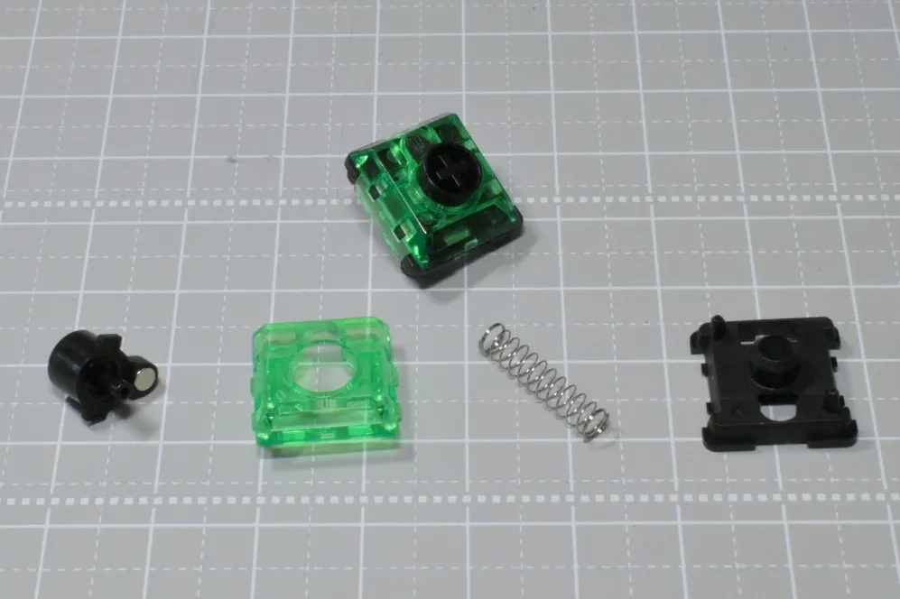
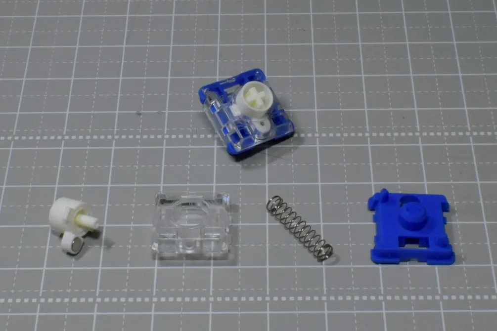
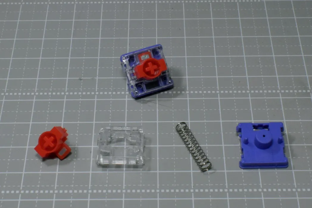
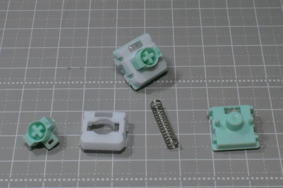
Below are photos and brief descriptions of the switches used. The caption values represent stroke length · actuation force · top-stem-bottom materials. I am particularly interested in switches with a 1.5 mm stroke — significantly shorter than a typical low-profile switch, and what I consider the centerpiece of this keyboard.
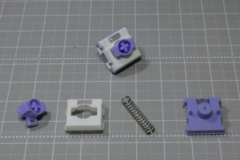
This looks like a TTC KOM Mini but is from a different manufacturer.
The TTC KOM MINI is absent because it is not sold individually. The Low-Profile Magnetic Gateron Jade / Jade Pro is available individually but at a considerably high price.
Sensors - DRV5055A3 / MT9102ET / GH39FKSW
These sensors were selected as test candidates because they are recommended by HE60 and because no publicly available comparative data or accuracy benchmarks between sensors could be found.
- DRV5055A3 — High price, but top-tier performance among the three. Befitting its TI automotive-grade rating.
- MT9102ET — Sensitivity and measurement range comparable to the DRV, at low cost. Spec sheet shows the shortest propagation delay of the three, which may give it an advantage in scan rate. Being a Chinese manufacturer, supply stability and support are concerns.
- GH39FKSW — Low price, but lower accuracy. Measurement range of ±650 G is narrow; saturation is possible depending on the switch used. Had I been able to obtain datasheets for all the switches, I could have narrowed the sensor selection considerably, but that was not possible this time, so comparing multiple sensors is the approach taken.
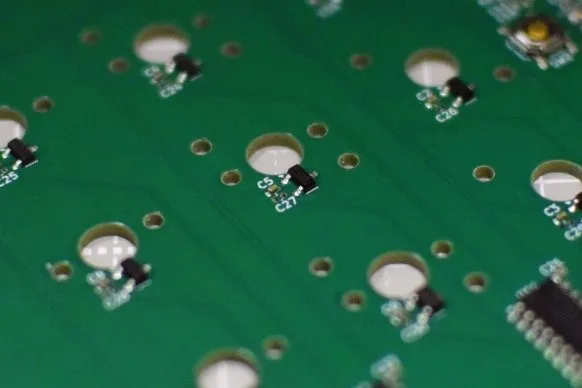
Filter Capacitors - 0 / 1 nF / 2.2 nF / 4.7 nF
Five boards were ordered. Four of them will be used to compare input precision across four filter capacitor values. These filter capacitors cut noise and stabilize the signal going into the ADC. A larger capacitance improves this effect, but comes with the trade-off of slower response. The goal is to experimentally determine the optimal capacitance for gaming use.
Design Highlights
Hybrid Footprint
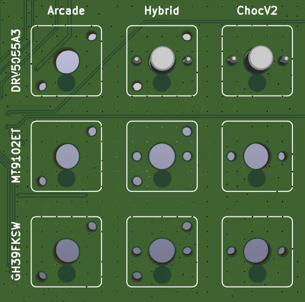
As described in the switch section, two footprint types are used in this project. A hybrid footprint was designed by overlaying both footprints so that either switch type can be installed.
Datasheets were not available for all switches, but those that could be obtained revealed that the center hole diameter differs by 0.2 mm and the Hall effect sensor position differs by approximately 0.2 mm between the two types. The diameter difference was resolved by designing to the larger value so both types can be mounted. A switch plate is not included in this test board, but the next design will include one, which should compensate for any slight wobble. The sensor position difference was split down the middle, placing the sensor 4.4 mm from center. Given the characteristics of magnetic force, a positional offset of this magnitude should allow both switch types to respond adequately, and firmware tuning can absorb remaining differences.
Those who have studied magnetism in high school physics may recognize this: magnetic force is inversely proportional to the square of the distance, meaning it increases sharply as distance decreases. The closer the sensor is to the magnet, the more sensitively it detects flux changes. Even with some sensor position variance, as long as the sensor is close enough, both switch types are expected to respond.
Separating 3.3V and 3.3VA
In PCB design, power rails are sometimes separated. Inside the MCU, digital and analog circuits coexist, and the digital circuits — GPIO switching, clocks, USB, etc. — inject switching noise onto the power rail. If a single unified power rail were used, this noise would interfere with the reference voltage and sensor circuitry, causing measurement variation and reduced accuracy. To prevent this, 3.3V (digital) is used for the MCU and MUX, while 3.3VA (analog) is used for the Hall sensors and other accuracy-critical circuits.
This is the same noise mitigation approach used in HE60. As with HE60, different LDO part numbers are used for 3.3V (digital) and 3.3VA (analog). However, in my design I unified the LDO part number. Benefits include consistent characteristics and easier behavior prediction since both are the same part, as well as a reduction in component variety. Regarding noise, there is an argument that using the same LDO part number for both digital and analog aligns their output characteristics, which is advantageous from a noise perspective — though no significant measured difference has been confirmed. Think of it as analogous to cable swapping in audio: the kind of improvement that may or may not be measurable in practice.
OLED
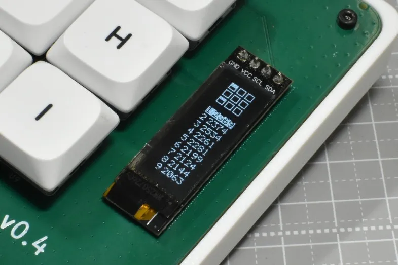
An OLED was added to this build. It is not strictly necessary for testing purposes, but I wanted to make something visually engaging to interact with. This small display shows the raw input value of each key along with a press animation corresponding to the keypress. Communication uses I2C via SDA and SCL, but the magnetic sensors cannot be read while display data is being transmitted. To minimize this impact, the OLED display update is designed to transmit in batches during gaps between sensor scans, so as not to affect the scan period.
SWD, UART, and Test Points for Debugging
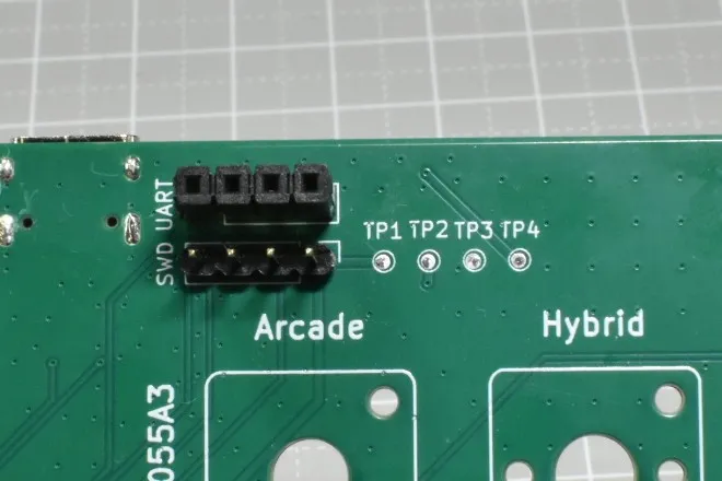
Since debugging is a primary purpose of this board, SWD, UART, and test points are all included.
SWD is used for firmware flashing and debugging of the MCU. It is used when USB DFU firmware flashing is unavailable, or when performing step-through debugging with breakpoints. A 4-pin header is provided for connecting a debugger such as STLink or J-Link.
UART is used for debug log output from the MCU. Sensor readings and firmware behavior can be streamed in real time to a serial monitor, making it invaluable during firmware tuning. A USB-to-serial adapter module is connected for use.
Test points expose metal pads for GND, 3.3V, 3.3VA, and 5V, allowing a multimeter to verify correct LDO operation.
Testing
Testing information will be added at a later date.
Conclusion
As this is a test board, it will not be sold, but if I attend events such as Gaming Bazar or Tenka-ichi Keyboard Waiwai-kai, I expect to have it on display. Thanks to the OLED, the keypress behavior is visually apparent, making it quite enjoyable to interact with.
About reRo
Below the ReBotLab brand icon, there is a logo reading reRo. This is the name of the organization I belong to at university. It is a place where members can freely work on a wide variety of making projects and share development progress and technical knowledge with one another.
The group primarily builds robots, with many members participating in competitions such as Micromouse, Line Tracer, and Microcontroller Car Rally. This board was reviewed by a senior member of the same organization, and I would like to take this opportunity to express my gratitude.