Archetype12
A test board for choosing the sensor in the next ReLow60 models: six sensor types on twelve keys, decided by measurement rather than datasheets. Not for sale.
Overview
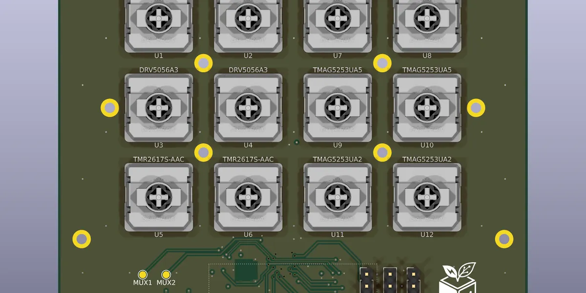
Archetype12 is a test board for deciding which sensor goes into the next ReLow60 models (US / Split / JP, and ReOrtho60). It succeeds the nine-key Archetype09; as before, the number is simply the key count — twelve.
Archetype09 answered the question “can a low-profile magnetic keyboard be built at all?” This board answers a narrower one: which sensor to ship — decided not from catalog figures but by measuring the candidates on the same board, with the same switches, under the same conditions.
It plays three roles at once:
- Sensor evaluation — six sensor types on one board, compared side by side for sensitivity, linearity, noise and temperature drift
- Plate-to-PCB gap optimization — sweeping spacer thickness to find the point where magnetic flux and switch retention are both satisfied
- Case-structure validation — the plate + spacer + PCB “core assembly” bolted together here is the prototype of the FSU (Fixed Sensing Unit) in the next models
As a test board it will not be sold. Like Archetype09, the design and measurement process is published as an engineering record. The board, plate and spacers were ordered in early September 2026 and are awaiting assembly.
Specifications
| Item | Detail |
|---|---|
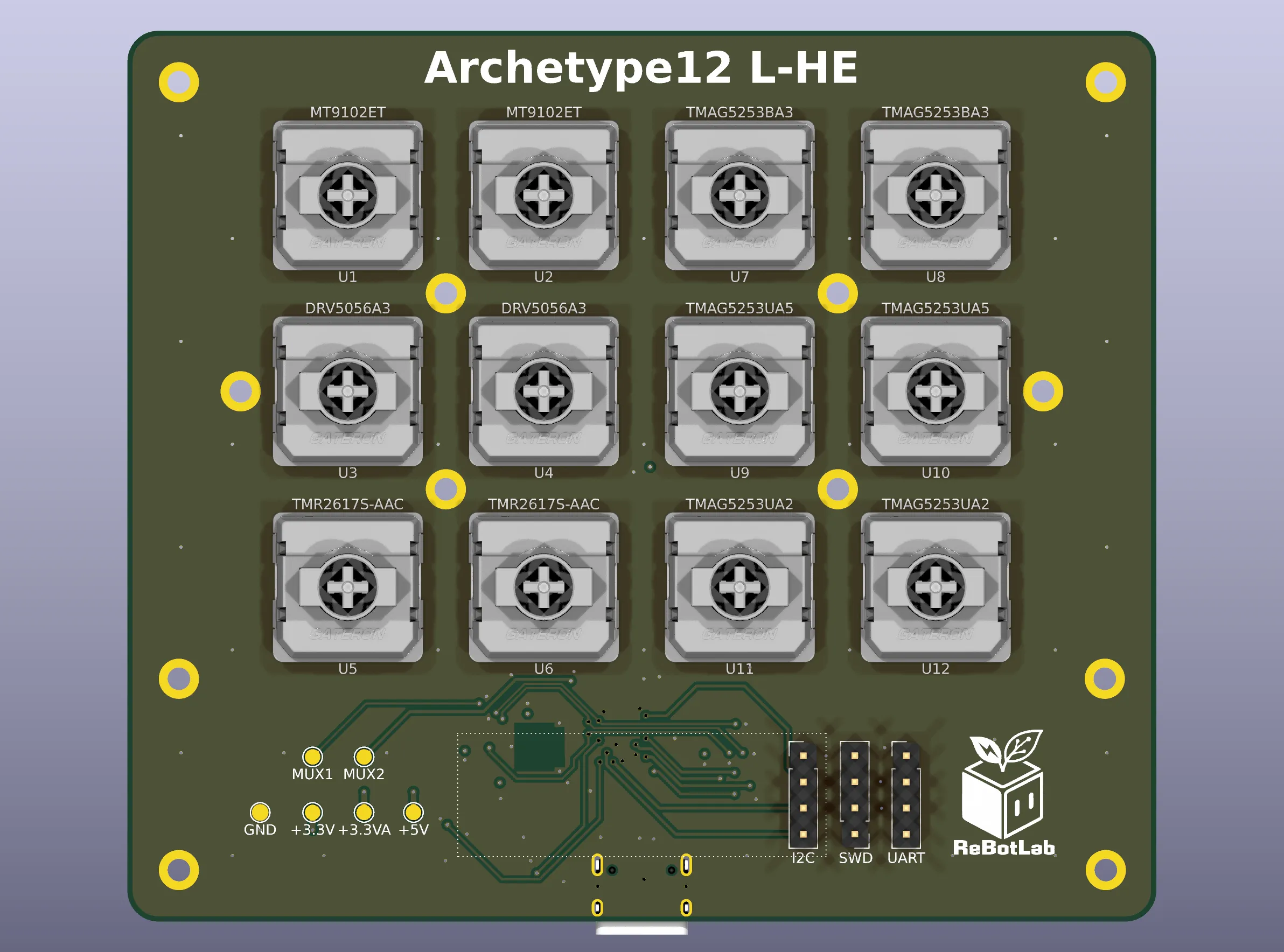
| Keys | 12 (3 rows × 4 columns, 19.05 mm pitch) |
| Board | 100 × 86.6 mm, R3 corners, 1.2 mm thick, 4 layers (JLCPCB) |
| Stackup | F.Cu / In1 = GND / In2 = +3.3VA / B.Cu — identical to the ReLow60 production board |
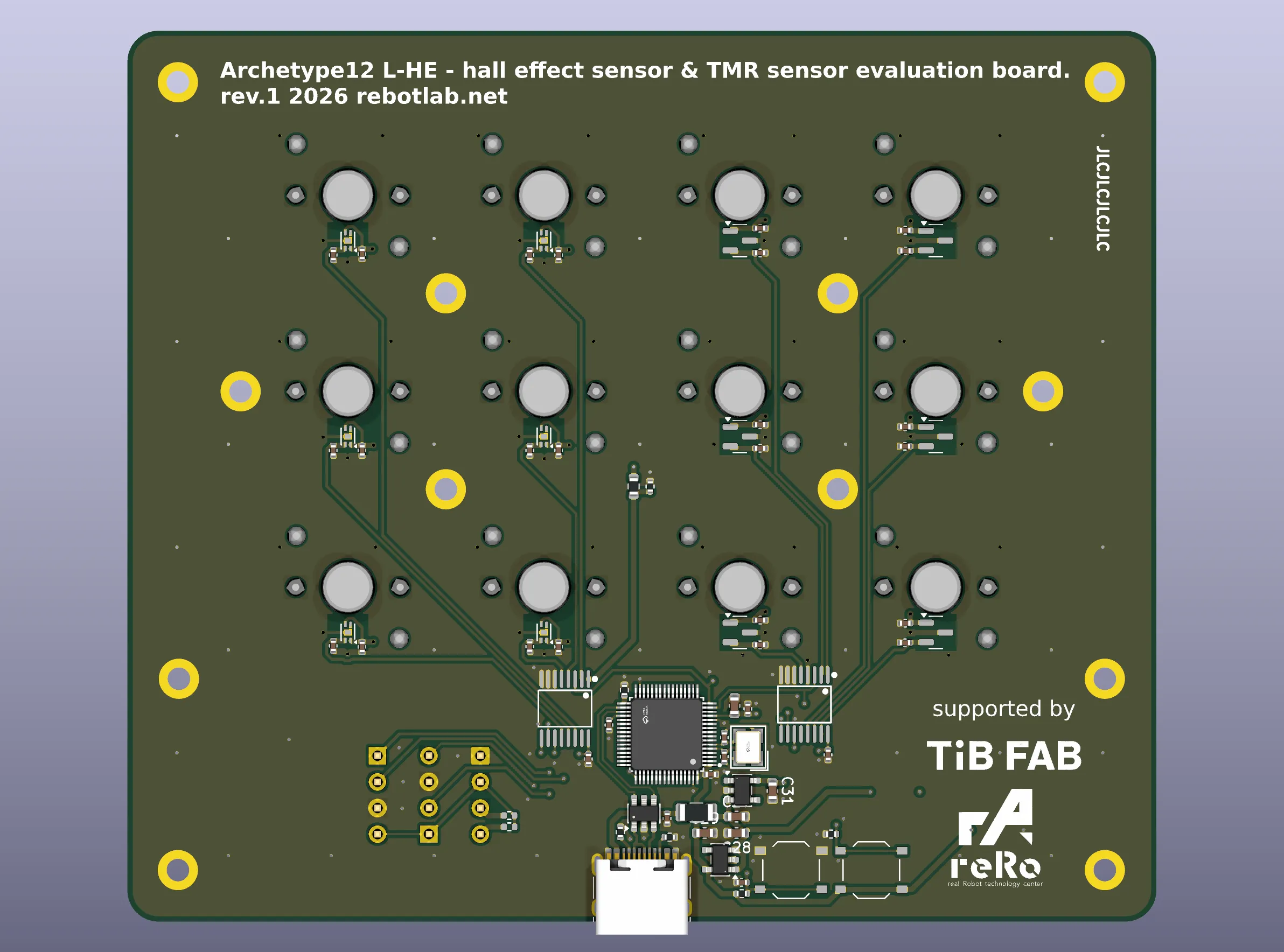
| Component side | Everything, sensors included, on the back side (B.Cu). The front carries only switches and mounting holes |
| MCU | AT32F405RCT7 (same as Archetype09, so the measurement firmware runs unmodified) |
| MUX / ADC | SN74LV4051A × 2 → PA1 / PA2 (12-bit ADC) |
| Sensors | SOT-23 × 6, X2SON-4 × 6 (see below) |
| Plate / spacer | FR4, 100 × 66 mm. Spacers in 0.8 / 1.0 / 1.2 mm |
| Fastening | M2 × 12, including holes at the points where four keys meet, so the board can be clamped right next to the keys whose gap matters |
| Debug | SWD / UART / I2C headers; test points for GND, +3.3V, +3.3VA, +5V and the MUX outputs |
| Display | Tester screens on an I2C OLED — per-key raw values, an overview, and temperature (not yet verified on hardware) |
| Primary switch | 1.5 mm travel (the choice of nearly every Limited Alpha buyer) |
Sensors under evaluation
| Footprint | Part | Qty | Role |
|---|---|---|---|
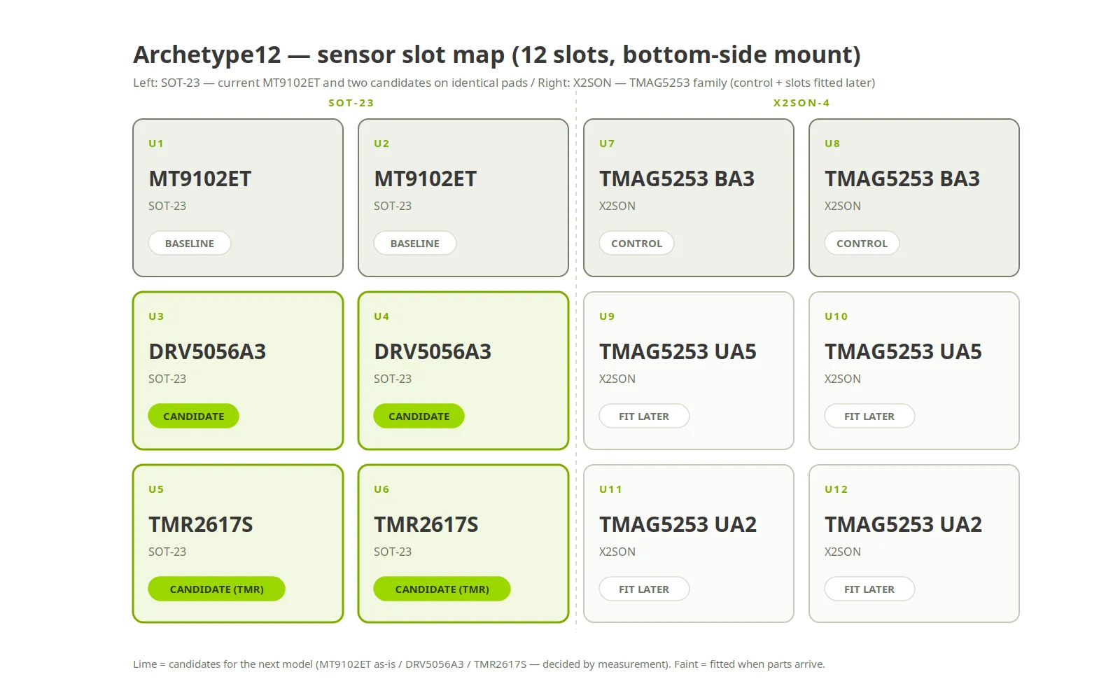
| SOT-23 | MT9102ET | 2 | Current part (used in the Limited Alpha). The baseline |
| SOT-23 | DRV5056A3 | 2 | Front-runner. About 1.9× the sensitivity, with built-in magnet temperature compensation |
| SOT-23 | TMR2617S-AAC | 2 | A TMR (tunnel magnetoresistance) sensor, 2–2.8× the sensitivity. Its hysteresis is the thing to measure |
| X2SON-4 | TMAG5253 BA3 | 2 | Bipolar control sample; also hand-soldering practice for X2SON |
| X2SON-4 | TMAG5253 UA5 | 2 | High sensitivity. Fitted into the spare slots once parts are available |
| X2SON-4 | TMAG5253 UA2 | 2 | Same die as UA5 with different gain; reference for polarity checks and extrapolation |
The shortlist for the next models is down to three: keep the MT9102ET, DRV5056A3, or TMR2617S. All three come in SOT-23 with the same pinout — 1 = VCC / 2 = OUT / 3 = GND — so they drop onto identical pads for comparison. It also means any of them can replace the current sensor on the production footprint without a redesign.
Only three criteria matter: resolution, temperature behaviour, and cost. Bipolar Hall sensors are already close to their physical ceiling with the MT9102ET; anything beyond it has to come from a unipolar part or from TMR.
Design notes
Four layers, because of the stackup
The flux a sensor reads passes through the copper of the inner layers on its way in. If the layer structure differs, numbers measured here no longer correspond to the production board. So Archetype12 uses the same four layers and the same layer assignment as the actual ReLow60 production PCB. Two layers would be cheaper, but it would defeat the purpose of the board.
Everything on the back
The front carries only the switches and mounting holes; sensors, multiplexers, MCU and power all live on the back. Back-side sensors mirror ReLow60, where the magnet-to-sensor distance is set by the board thickness (1.2 mm). Each multiplexer sits directly under the columns it serves, keeping the twelve analog traces as short as possible.
The circuit starts from a schematic map
Rather than copying the Archetype09 circuit, Archetype12 started from a “schematic map” — a single document of every connection and design decision — and the circuit was drawn from that. ERC reports zero issues, and the netlist was checked mechanically against the map with a full match. The KiCad library tables ship with the project, so a fresh clone opens on someone else’s machine as-is.
Measurement plan
Measurements are split into two groups. A mixed board invites the worry that neighbouring sensors heat each other, or that heating is uneven — the grouping is what sidesteps both.
| Group | What | How |
|---|---|---|
| Electrical | Polarity, sensitivity, linearity, noise, coverage, effective resolution | Room temperature. Neither neighbour heating nor oven uniformity matters, so one mixed board is enough |
| Self-heating | — | Not measured individually. The current MT9102ET (6 mA) was soaked for five hours and drifted at most 4 LSB — a non-issue. Parts drawing the same current or less reach the same conclusion |
| Ambient temperature | LSB/°C per part (zero drift, effect of magnet compensation) | Heat the whole board uniformly. First pass on a hot plate, then a proper run in an environmental chamber. A single thermocouple acts as a monitor, not a heater |
Every key is measured pressed to bottom-out. Archetype09 was measured on partial travel with a height gauge, which hid saturation — that mistake will not be repeated.
Next steps
- Assemble on a hot plate once the boards arrive (no parts on the front, so a single bottom stencil)
- Measure group 1 (electrical), then group 2 (ambient temperature)
- Sweep the 0.8 / 1.0 / 1.2 mm spacers to relate gap to flux and switch retention
- Fix the sensor and spacer thickness for the next models from the results
Results will be appended here or written up separately.
Summary
Where Archetype09 asked whether the board could be built, Archetype12 asks what to build it with. It will not be sold, but it will be on the table at events; the OLED shows each key’s live reading, so the differences between sensors can be felt and compared by hand.
The back of the board carries the logos of TiB FAB, who support the project, and reRo, the university group I belong to. The ambient-temperature run is planned on TiB’s environmental test chamber.